
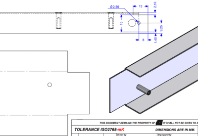
When a technical drawing of a part is prepared, in order to define its precision tolerances to the nominal dimensions and tolerances should be specified. To avoid designer having to specify tolerances for every dimensions and help manufacturers to easily asses the difficulty of manufacturing, the International Organisation for Standardization (ISO) published a general tolerance norm : the ISO 2768.
On a drawing mention of the standard designation + two letters : for example ISO 2768-mK or ISO 2768-fH, means that the intent of the designer was that all non otherwise specified tolerances on the drawing will have to respect below charts values.

ISO 2768-1 general dimensional tolerances
The first part of the norm refers to the general tolerances, which are the linear and angular dimensions without other tolerances on the specifications.
| Reference | Description | 0.5 to 3 | 3 to 6 | 6 to 30 | 30 to 120 | 120 to 400 | 400 to 1000 | 1000 to 2000 | 2000 to 4000 |
|---|---|---|---|---|---|---|---|---|---|
| f | Fine requirement | ±0.05 | ±0.05 | ±0.1 | ±0.15 | ±0.2 | ±0.3 | ±0.5 | – |
| m | Medium requirement | ±0.1 | ±0.1 | ±0.2 | ±0.3 | ±0.5 | ±0.8 | ±1.2 | ±2 |
| c | Coarse requirement | ±0.2 | ±0.3 | ±0.5 | ±0.8 | ±1.2 | ±2 | ±3 | ±4 |
| v | Very coarse requirement | – | ±0.5 | ±1 | ±1.5 | ±2.5 | ±4 | ±6 | ±8 |
| Reference | Description | 0.5 to 3 | 3 to 6 | More than 6 |
|---|---|---|---|---|
| f | Fine requirement | ±0.2 | ±0.5 | ±1 |
| m | Medium requirement | ±0.2 | ±0.5 | ±1 |
| c | Coarse requirement | ±0.4 | ±0.5 | ±2 |
| v | Very coarse requirement | ±0.4 | ±1 | ±2 |
| Reference | Description | Up to 10 | 10 to 50 | 50 to 120 | 120 to 400 | More than 400 |
|---|---|---|---|---|---|---|
| f | Fine requirement | ±1° | ±0°30’ | ±0°20’ | ±0°10’ | ±0°5’ |
| m | Medium requirement | ±1° | ±0°30’ | ±0°20’ | ±0°10’ | ±0°5’ |
| c | Coarse requirement | ±1°30’ | ±1° | ±0°30’ | ±0°15’ | ±0°10’ |
| v | Very coarse requirement | ±3° | ±2° | ±1° | ±0°30’ | ±0°20’ |
ISO 2768-2 geometrical tolerances
The second part of the norm is about geometrical tolerances, like perpendicularity, flatness, straightness etc.
Please note that the general dimensions tolerances applies for roundness (through the diameter value) and parallelism.
| Reference | Up to 10 | 10 to 30 | 30 to 100 | 100 to 300 | 300 to 1000 | 1000 to 3000 |
|---|---|---|---|---|---|---|
| H | 0.02 | 0.06 | 0.1 | 0.2 | 0.3 | 0.4 |
| K | 0.5 | 0.1 | 0.2 | 0.4 | 0.6 | 0.8 |
| L | 0.1 | 0.2 | 0.4 | 0.8 | 1.2 | 1.6 |
| Reference | Up to 100 | 100 to 300 | 300 to 1000 | 1000 to 3000 |
|---|---|---|---|---|
| H | 0.2 | 0.3 | 0.4 | 0.5 |
| K | 0.4 | 0.6 | 0.8 | 1 |
| L | 0.6 | 1 | 1.5 | 2 |
| Reference | Up to 100 | 100 to 300 | 300 to 1000 | 1000 to 3000 |
|---|---|---|---|---|
| H | 0.5 | 0.5 | 0.5 | 0.5 |
| K | 0.6 | 0.6 | 0.8 | 1 |
| L | 0.6 | 1 | 1.5 | 2 |
ISO 2768 usages
The tolerance ISO norm is very popular for metal sheet parts, precision machining parts and plastic injection parts designing. Casting parts usually use different tolerance norms for the raw casting parts.
Are the tightest tolerances always better?
Parts designed with tightest tolerances will be closer to nominal values and therefore easier to integrate with other parts in mechanical assemblies. But tighter tolerances means more difficult parts to manufacture and therefore more expensive parts. In order to have effective design to cost approach, tolerance requesting should be matched with manufacturing means default capabilities, functional usage and assembly constraints.
Recommendations
Usage of the ISO 2768 norm is very widespread and convenient, but you should not forget that too loose or too tight tolerancing on your drawings will impact the feasibility of your parts.
The ISO standard version used for this article is 1989, please be aware that new version may be published in the future. In 2021, ISO 2768-2:1989 as been withdrawn and replaced by ISO 22081:2021.

